| NAQCC News |
| KX-1 Project Special | NAQCC Web Site | Issue # EXTRA | |
|---|---|---|---|
KX-1 Project - Complete INTRODUCTION: - By NAQCC President Tom WY3H - Outside of CW operation perhaps there is nothing that represents the heart of Amateur Radio as home brewing (hey, we're talking radio gear, not liquid refreshments - that can come later) and we must also include kit building. Recently two NAQCC members, our V.P, John, K3WWP, and Mike, KC2EGL, decided to get in touch with their radio "roots" by building an Elecraft KX-1. Now years ago, a home brew rig could be constructed almost entirely from parts found in any respectable operator's junk box. Most were "one-tube" jobs and, being "real radios," they "glowed in the dark". The impromptu rigs could be surprisingly effective - and a whole lot of fun. A surprising number are still heard on the air today. However, almost needless to say, times have changed. Simplicity is somewhat relegated to history. We live in the age of digital technology replete with CMOS components and mounds of small parts that go into one transceiver. Such is the case with the KX-1. However, most anyone will agree that today's radios are a far cry from those tube rigs of yesteryear. They are more energy efficient, more stable, have "dead-on" frequency, require little or no warm up time, they have features not even dreamed about by some of the old time hams, and most important, they are light, rugged and completely portable. After Mike acquired an Elecraft K-2, he thought it would be nice to have a KX-1 to take to remote operating sites or for general portable (mobile) use. Mike wisely decided to enlist the aid of John, K3WWP to help him with the ambitious undertaking. When the kit arrived Mike drove from his home QTH in Brookville, Pa. to John's house in Kittanning. They eagerly opened the box and the first step was to inventory the 200 or so small parts that comprise a KX-1. Kit part inventory is a critical first step in any such project. And as Mike and John discovered, the task is not always as simple as it seems. A careful inventory indicated that two small, but non-critical parts seemed to be missing, a small screw and an equally small pin. However, after removing a battery clip from a hermetically sealed plastic bag, the missing parts were discovered "hiding" in the clip. With the parts now inventoried and meticulously separated in several empty egg cartons (a great way to store and separate small electronic parts). Construction was about to begin. John will pick up that part of the story, however, there is one final note of interest and encouragement to anyone thinking of building their first kit. John's "work shop" does not consist of a fancy workbench with multiple electrical outlets, and shelves full of specialized test equipment. No, kits like the KX-1 do not require elaborate test equipment. For almost all of the testing all that's needed is a simple, low cost, multimeter and a simple dummy load*. Later, a final alignment of the KX-1 will be done with John's Kenwood 480 transceiver. It may also be a good idea if you're handling CMOS components to invest in an anti-static wrist strap and perhaps a grounded-tip soldering iron (I got my iron from Radio Shack for $8.99). By the way John's "workbench" is a simple folding card table set up in his dining room. He added a small goose neck lamp and of course, a few simple hand tools, such as needle nose pliers and small nippers, a manually operated solder vacuum and a few screwdrivers. Today's kits aren't "simple" when compared to home brew tube rigs of several decades ago, however, building them is not a complicated process - it's time consuming, but not necessarily complicated. *Mike and John are building two Elecraft dummy loads kits. PART 1: - Remember the excitement involved in the anticipation of that first date with the beautiful girl in high school? Or buying your very first car? Anticipation is the very first part of any project whatsoever. 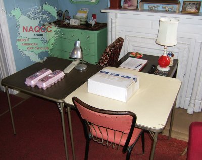 Our anticipation and excitement are peaking right now as we are about to open the box and begin our adventure. No, that's not our breakfast in those egg cartons. They are a convenient way to store kit parts for handy access. Put all resistors, capacitors, or transistors of the same value in one of the compartments, and they are easy to grab when the time comes to install them. 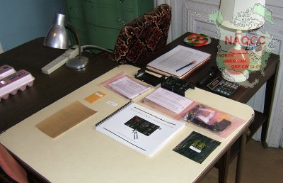 As with any kit building project the very first step should always be a complete inventory of the parts. It's very frustrating to get the kit 75% built and then find there is a part missing. It's best to find out before you start building, so any missing parts can be ordered then. The particular kit we are building includes the basic KX-1 plus the accessory boards for 80/30 meters and the automatic antenna tuner.
The parts for each unit come in the three pinkish plastic bags. Also shown are the main chassis box top and bottom, the main circuit board, the complete manual, a mini manila envelope with the serial number sticker, and a big piece of sandpaper (huh?). More about the sandpaper later on. 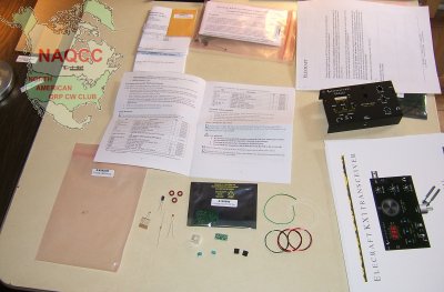 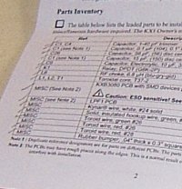 We decided to start with the inventory of the 80/30 accessory parts. Each accessory comes with its own manual including a parts check list. We spread out the parts, checked them off on the list as we identified them, and replaced them in the plastic bag. 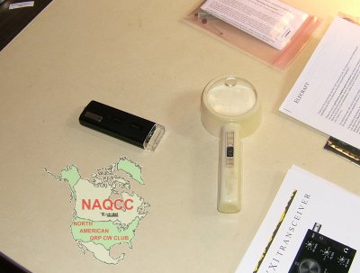 It quickly became apparent that the two items shown here were to be an important part of our project. As eyes get older and parts get smaller, it becomes increasingly difficult to read the miniscule part numbers on the components. We often used the magnifier, and on occasion had to even resort to the small 30X mini-microscope to read some of the numbers. 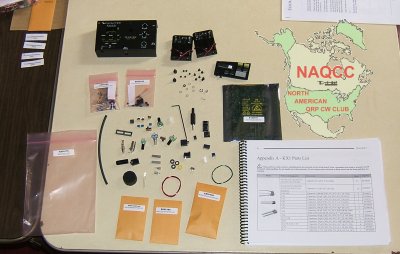 Having finished the inventory of the 8030 and ATU modules, we began on the main circuit board and enclosure. This picture shows clearly how small some of the parts are. Some of the ones in the little bags are even smaller. 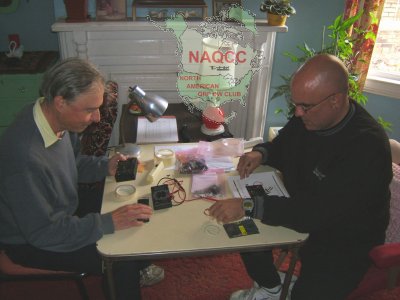 Here are the intrepid builders, John (left) and Mike wrapping up the inventory. We discovered that two parts were missing, a tiny bolt and a clip that inserts into a plastic shell to form a plug. We sent off an email to Elecraft who immediately responded saying they would ship the missing parts. Elecraft has one of the finest support teams around. However, as we were putting the parts away, the 'missing' clip fell out of the spring in the battery holder. An examination of the second battery holder also turned up the 'missing' bolt, stuck firmly in the spring, and needing some persuasion to release it. So we emailed Elecraft again and explained the situation. All parts were present and accounted for. We did learn that when dealing with such tiny parts that they can be hidden in little nooks, crannies, and springs of the bigger parts. That and learning that you needed some high magnification to identify some parts were the two lessons we took from the first session of our project. Subsequently Mike ordered a 20 watt dummy load from Elecraft. In fact, two of them, one for his home station K2 and one for portable operation with the KX-1. PART 2: - Mike KC2EGL showed up at my (K3WWP) house early on Saturday, November 29th just about the time I finished up my daily NAQCC chores along with my personal web site updates. He had his two dummy load kits with him. Those would start our work for today.  We spread the parts from the first of the two kits out on the table to be sure everything was there and in good shape. Everything was OK, so we moved on. We set up our working light, soldering iron, a newspaper to protect the card table surface from stray solder, and a damp paper towel to keep the soldering tip clean. 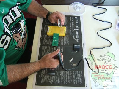 Here's a historic moment in our project. It's Mike making the very first solder connection, fastening the BNC connector to the printed circuit board. Construction of the board went smoothly. The only thing worth mentioning in the process is it took Mike a couple solder connections to get used to using the right amount of heat and solder. That's probably one thing that everyone dealing with soldering for the first few times needs to get used to. After that, it becomes second nature. The only part that needed any minor special attention was the diode used to pick off the RF voltage from the dummy load for measurement. Of course polarity of the diode had to be observed, but that was easy because the ends of the diode were clearly marked as was its location on the board. Also I told Mike that this solder joint had to be made quickly since diodes are more sensitive to heat than any of the other parts on the board. 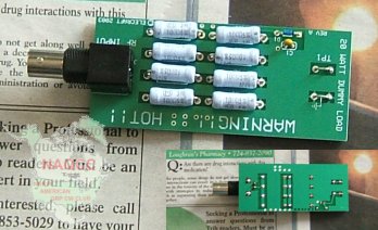 After the final step of mounting the 4 rubber feet to the board, we wound up with this neat little unit. The top and bottom views (before mounting the feet) show clearly that Mike did a great job on his first complete printed circuit board. We took a break in the project to go work some DX in the CQWW DX Test, then got back to construction. 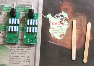 With one board under his belt, Mike zipped through the second board quickly, and we wound up with these two nice looking units, one of which will be used with Mike's K2, and the second with the KX-1. If you have any amount of curiousity whatsoever and don't already know, the popsicle sticks are not remants of our lunch, but are a 'vital' part of kit construction. Being approximately 1/16 inch thick they are an ideal spacer for mounting the power resistors that distance above the circuit board to prevent the heat from the resistors from damaging the board when the unit is in use. With that, we quit for the day so Mike could get home and do some Christmas decorating. PART 3: - Mike returned Monday morning, December 1st to continue work on the project. We planned to build the Antenna Tuning unit with the thought in mind, as with the dummy loads, we'd start with the smaller accessory boards for Mike to get some experience working with the different parts before tackling the main KX-1 board. That turned out to be a good idea as the ATU board contained a good sampling of most of the components involved in building the main board. 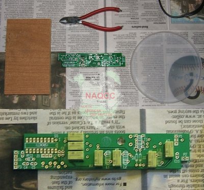 The first parts to be mounted were the 7 relays that switch in and out the various combinations of caps and coils to do the actual 'tuning' of the antenna. All seven were mounted on top of the board which was then turned over on a flat piece of wood to hold the relays against the board while soldering them. As with many of the parts with multiple leads, the procedure was to solder just one of the leads, then check to see the part was firmly seated on the board before soldering the other leads. In this case six of the seven came out just fine, but one had to have its one pin heated again to re-position it solidly against the board. The plastic lid from a butter container is a handy thing in which to catch and store the excess lead length of components as they are cut off. The diagonal cutters shown did not cut the leads as close to the board as possible, and we wound up at Radio Shack to purchase a pair of flush cutting 'dikes' which worked much better as it is very important in working with such compact units as the KX-1 to keep everything as close to the board surface as possible. After the relays were soldered in (a total of 56 solder connections), an assortment of other parts were installed following either the same procedure as used with the relays 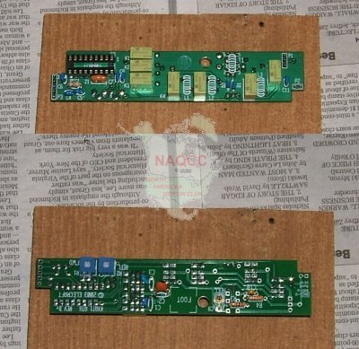 or in the case of components with just two leads, mounting them on the board, bending the protuding leads slightly to hold the part in place, making the solder connections, and trimming off the excess lead lengths. The parts connected here included an IC socket, some resistors, diodes, a ceramic resonator, variable resistors, an RF choke, a trimmer capacitor, and capacitors. Some parts as shown were mounted on the bottom of the board. Most of that was straightforward. We had to be careful with the ceramic resonator (Z1 near the IC socket) as it is fairly heat sensitive and had to be soldered quickly. By this time however Mike had become so proficient at soldering that was no problem. We did pause briefly between each of the 3 solder connections though, just to let the resonator cool a bit. Better safe than sorry as the saying goes. Mounting 3 of the caps on the bottom (C1, C2, C3 near the middle) was also a bit tricky as they had to be mounted slightly above the board so they could then be bent down against the board at a 45 degree angle or so to keep them from sticking up too high. or in the case of components with just two leads, mounting them on the board, bending the protuding leads slightly to hold the part in place, making the solder connections, and trimming off the excess lead lengths. The parts connected here included an IC socket, some resistors, diodes, a ceramic resonator, variable resistors, an RF choke, a trimmer capacitor, and capacitors. Some parts as shown were mounted on the bottom of the board. Most of that was straightforward. We had to be careful with the ceramic resonator (Z1 near the IC socket) as it is fairly heat sensitive and had to be soldered quickly. By this time however Mike had become so proficient at soldering that was no problem. We did pause briefly between each of the 3 solder connections though, just to let the resonator cool a bit. Better safe than sorry as the saying goes. Mounting 3 of the caps on the bottom (C1, C2, C3 near the middle) was also a bit tricky as they had to be mounted slightly above the board so they could then be bent down against the board at a 45 degree angle or so to keep them from sticking up too high.Next came a procedure that I had only done once or twice in my life, and Mike had never done - winding toroids. 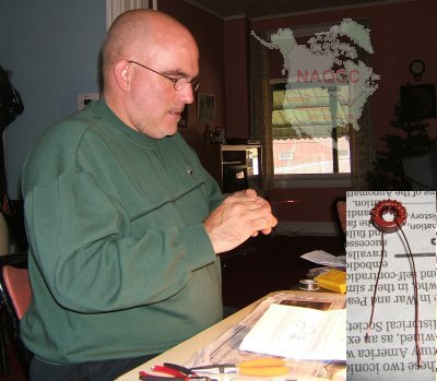 We followed the instructions exactly (or so we thought) and got the first one wound. You can see how Mike was concentrating on the winding. The inset shows the toroid after Mike finished it. Then the leads had to be trimmed to 1/2 inch and 3/8 inch of the enamel had to be removed. That proved to be a bit tricky. There are several ways of removed the enamel. We decided to try the heat method. We held the toroid in a clamp improvised from our two popsicle sticks and a rubber band, then applied a match to the end of the wire which burned off the enamel. Then (remember the picture in the previous installment?) the sandpaper was used to clean the ends of any remaining enamel or residue. When that was all done it turned out the windings were done in the wrong direction as we found out when trying to mount it on the board. Of course that wouldn't matter as far as inductance goes, but it was just too awkward to mount it in the tight space with the leads exiting the toroid in the wrong direction. So Mike unwound it and did it again in the right direction. After it was corrected and mounted, Mike moved on through two more toroids, each with more turns (17 and 25) than the first 12 turn one. We followed the instructions exactly (or so we thought) and got the first one wound. You can see how Mike was concentrating on the winding. The inset shows the toroid after Mike finished it. Then the leads had to be trimmed to 1/2 inch and 3/8 inch of the enamel had to be removed. That proved to be a bit tricky. There are several ways of removed the enamel. We decided to try the heat method. We held the toroid in a clamp improvised from our two popsicle sticks and a rubber band, then applied a match to the end of the wire which burned off the enamel. Then (remember the picture in the previous installment?) the sandpaper was used to clean the ends of any remaining enamel or residue. When that was all done it turned out the windings were done in the wrong direction as we found out when trying to mount it on the board. Of course that wouldn't matter as far as inductance goes, but it was just too awkward to mount it in the tight space with the leads exiting the toroid in the wrong direction. So Mike unwound it and did it again in the right direction. After it was corrected and mounted, Mike moved on through two more toroids, each with more turns (17 and 25) than the first 12 turn one.A final toroid winding involved making a transformer. The previous ones were simple inductors. The transformed involved a double winding consisting of a twisted pair of wires. That went smoothly, but the stripping of the ends was a little more tricky since the manual advised against using heat since it may melt more of the enamel than needed and short the twisted pair together. So Mike laboriously used just the sandpaper to strip the 4 leads. On the transformer it was also suggested to tin the leads before installing it. We used our makeshift clamp to hold the toroid while Mike tinned all the leads. Finally all the toroid work was completed and provided some good practice for the later toroid work in the kit. That was pretty much it except for putting the IC microcontroller in its socket. It is static sensitive so Mike made sure he discharged any static from his body by touching the metal legs of the card table and the metal lamp before proceeding. The leads on the IC were bent out just a little too wide to go in the socket, so I showed Mike how to bend them all at once by using the flat surface of our little board. After they were straightened, the IC went in smoothly. Here's a top and bottom view of the final product with our improvised popsicle stick clamp shown alongside. 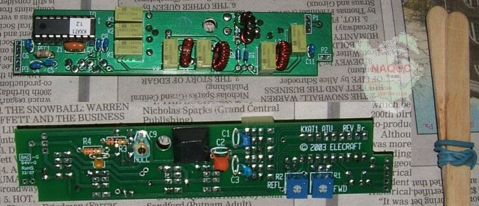 With time out for lunch and a couple other chores, building the ATU took up most of the day. Importantly though, Mike picked up a lot of experience with various components and techniques. I see him as a lot more confident now than when we first started on our first board. Next, on a yet to be decided day, we'll build the 8030 accessory board, then after that, get started on the main KX-1 board. PART 4: - January 20 was a memorable day for the NAQCC. Mike KC2EGL and John K3WWP resumed work on the NAQCC KX-1 Kit building project. As you know from a previous newsletter, Mike KC2EGL is an employee of the USPS, and also lives some 40 miles from K3WWP so there haven't been many opportunities of late to get together. However Mike took a vacation week, and with the weather being agreeable, we put in several sessions of work.  Before we started on the main KX-1 board, we made up a couple cables for the dummy loads we constructed previously. Neither of us had used solderless BNC connectors before, and were very impressed with the ease of installing them on coax. One note of caution though - don't overtighten the screw that makes contact with the coax shield as that can lead to a short between the shield and center conductor. Before we started on the main KX-1 board, we made up a couple cables for the dummy loads we constructed previously. Neither of us had used solderless BNC connectors before, and were very impressed with the ease of installing them on coax. One note of caution though - don't overtighten the screw that makes contact with the coax shield as that can lead to a short between the shield and center conductor.Most of the work went pretty much straightforward. If you decide to build a KX-1 or any kit for that matter, always be sure to follow the assembly manual exactly. It may seem illogical at times to do some things in a certain way, but there is rhyme and reason behind everything in that manual. If some section of a manual involves several steps in installing a component, but sure to read and understand all the steps before doing anything with that component. 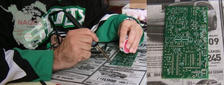 Here's Mike making the ceremonial first solder connection on the main KX-1 board and the result - the resistor in the lower right corner. There are a few surface mount components that are pre-installed on the board. Here's Mike making the ceremonial first solder connection on the main KX-1 board and the result - the resistor in the lower right corner. There are a few surface mount components that are pre-installed on the board.A couple members expressed concern that we weren't doing enough to prevent static damage to sensitive parts. While not apparent from the photos, the card tables we are working on have a metal frame that acts as a very good ground as we are in contact with it most of the time. When we get to an extra sensitive part, we also touch the frame several times while working with it as an extra precaution. Let's talk a bit about some things specific to the KX-1 kit, then a couple more general tips. The KX-1 comes with two 68pf caps. If the two are different sizes, be sure to install the correct one in the correct place. When you run into the installation of the first 68pf cap, read that step carefully. If you gloss over it, it's easy to use the wrong one. The smaller one fits in a very cramped tiny space. If one of yours is bigger, it won't fit there. When you get to mounting the antenna jack J2, it requires a lot of heat because the metal frame of the jack acts as a heat sink. The manual recommends using a higher wattage soldering iron for the jack, but Mike and I found that using 2 smaller irons on the pin simultaneously also works very well. With just the center pin of J2 soldered, it's a good time to 'dry fit' the board into the case. That allows you to re-position J2 slightly if it doesn't exactly fit into the round hole of the case before you make the final 2 connections - the ones that require the extra heat. Once they are soldered, it is hard to desolder and adjust. The dry fit also allows you to see if any parts are mounted too high on the board. Real estate is at a premium in the KX-1, and if a part sticks up from the board too far, it won't go in the case properly. That is stressed consistently throughout the manual. We did find one cap that was too high. We had to de-solder it, adjust its leads, and push it closer to the board. 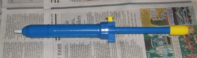 Always have a very good solder sucker while building the KX-1 or any kit. One of the easiest ways to damage a PC board is de-soldering and re-soldering a connection. A good solder sucker allows the process to take place quickly without overheating the board. This is one that was given to me by Tom WY3H about a year ago. It's the best one I've ever used. Always have a very good solder sucker while building the KX-1 or any kit. One of the easiest ways to damage a PC board is de-soldering and re-soldering a connection. A good solder sucker allows the process to take place quickly without overheating the board. This is one that was given to me by Tom WY3H about a year ago. It's the best one I've ever used.One other general tip that may be obvious is to use a heat sink if you happen to be soldering a temperature sensitive component with a long enough lead to be able to use one. With PC board kits, most component leads are too short for this, so the solder connection must be made as quickly as possible. However if you do need a good heat sink, one can be quickly improvised by using needle nose pliers with a rubber band to hold them closed like a clamp. 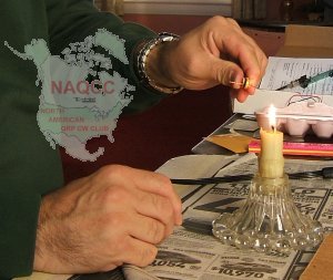 In winding the toroids, there are three ways suggested in the manual for removing the enamel from the wire - heat, solder, and scraping. We found the heat method to work best. Mike came up with a great way of applying that heat. Use a candle in a candlestick holder. It more or less adds an extra hand to the process since it is a stable source of heat rather than trying to hold a lighter or a match. In winding the toroids, there are three ways suggested in the manual for removing the enamel from the wire - heat, solder, and scraping. We found the heat method to work best. Mike came up with a great way of applying that heat. Use a candle in a candlestick holder. It more or less adds an extra hand to the process since it is a stable source of heat rather than trying to hold a lighter or a match.After a couple hours of careful, learning assembly, we arrived at the first 'alignment and testing' section of the manual for the display and microprocessor section of the rig. So far, so good as you see here with the LED display working as it should and no smoke pouring from the circuit board. 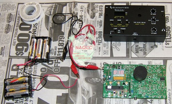 After using the batteries as a power source, we found a 12 volt power cube in my junk box and used that from then on. PART 5: - After working on the kit 3 days during the week (Tue, Wed, Thu), Mike returned on Sunday for a little more work. At the end of our Thursday session, we had trouble tuning the tiny trimmer caps on the board for lack of a proper tool. Mike brought a couple tools with him this day, but we finally wound up just winding some electrical tape around a regular miniature screwdriver. Another problem was that we hadn't turned the filter pot up all the way. As soon as we did that, the peaks in noise were much easier to find. The one 20M trimmer cap does have a very broad peak and it was hard to find the exact center of the peak by ear. 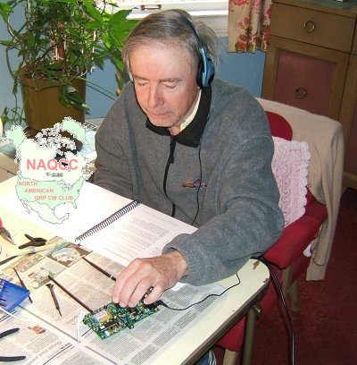 At any rate we did get the trimmers adjusted, hooked up a mobile whip that Mike brought and tuned around the band. All of a sudden 40M lost its noise and I was hearing CW signals! It took us a bit to realize that the noise we were hearing was being generated my microprocessor controlled furnace, and the signals appeared when the furnace heating cycle ended. 40M was full of signals, some quite strong. That was a relief and somewhat exciting to know at least the receiver section of the kit seemed to be working in fine shape. You can see John very absorbed in tuning around in this picture Mike took unexpectedly. I believe the actual first signal we heard was K4EJQ around 7.040. At any rate we did get the trimmers adjusted, hooked up a mobile whip that Mike brought and tuned around the band. All of a sudden 40M lost its noise and I was hearing CW signals! It took us a bit to realize that the noise we were hearing was being generated my microprocessor controlled furnace, and the signals appeared when the furnace heating cycle ended. 40M was full of signals, some quite strong. That was a relief and somewhat exciting to know at least the receiver section of the kit seemed to be working in fine shape. You can see John very absorbed in tuning around in this picture Mike took unexpectedly. I believe the actual first signal we heard was K4EJQ around 7.040.Now that the microprocessor and receiver circuits were assembled and working, we moved on to the transmitter section. As in the previous sections, assembly went smoothly for the most part thanks to the well written manual. Mike had to wind a toroid that had two separate windings on it. That was a little tricky, and while he was winding, I was thinking it was going to be a little difficult identifying which wire was which when he mounted it on the board. I thought leaving the 4 leads different lengths might work, so we made lead 1 the shortest and worked up to lead 4 being the longest. That worked very well. We were now at the final assembly steps and our first real major difficulty. Mounting the battery holders, while sounding like being an easy step, was quite a problem. The 2-56 screws supplied with the holders just weren't long enough to grip the threaded holes in the case. After trying and trying with no success, we raided my junk box of several hundreds (thousands?) of assorted screws and found a couple with the correct threads but longer. That worked well, but the screws will have to be cut off when Mike returns again. We couldn't get to the final testing of the rig because of the delay with the battery holders. Mike had to leave for a dinner engagement before we could do any testing. That was a bit frustrating for both of us, but couldn't be helped. Our next session will be on President's Day, February 16th when we should wrap up the main KX-1 kit and at least get started on the 8030 accessory board. Maybe even get it finished. PART 6: - We still have a couple folks questioning why it is taking so long to complete our KX-1 project. The answer is simple. As you know from a previous newsletter, Mike KC2EGL is an employee of the USPS who works a full 40 hour week, and also lives some 40 miles from K3WWP so there haven't been many opportunities of late to get together, especially with the rough weather we've had in Western PA this winter. We did have another successful few hours together on Sunday, February 15. Let's describe now what happened that day. 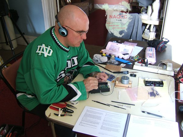 We set up our worktable and the rig for the final alignment and testing of the transmitter section with a dummy load. That went smoothly, and after re-peaking the receiving section as instructed in the manual which Mike is doing here, we were hearing a lot of RTTY stations in the CQWW RTTY contest on 20M and some CW sigs as well on 20 and 40. All we were using for an antenna was one of Mike's mobile 20M whips in the first floor of my house. In one of our first sessions we built the ATU (Antenna Tuning Unit), and our next step now was to install it on the main KX-1 circuit board. That went smoothly, and we wound up with the rig now looking like this. 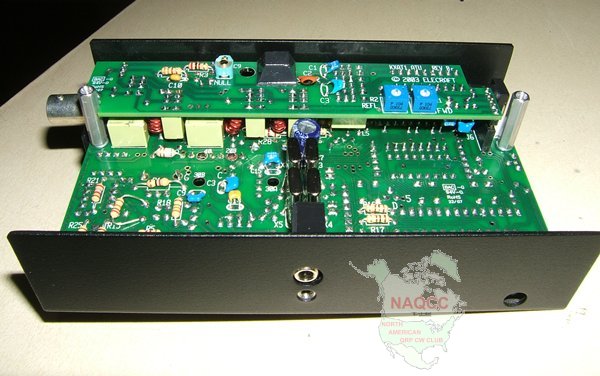 A check-out of the tuning unit started with a vivid demonstration. When Mike put on the phones to listen and turned on the rig, he was blasted with a great increase in volume over what it was with just a jumper in place of the ATU. After he recovered from that blast we continued. The check-out procedure showed that all of the relays in the ATU were functioning perfectly. The next step was moving on to the 80/30 meters accessory board. The first thing in that manual was to modify the main KX-1 board to accept the 80/30 unit. That proved to be perhaps the hardest part of the project so far. What made it hard was removing or removing/replacing several parts from the board. Even with a fine tip soldering iron and the wonderful solder sucker pictured in the last installment, getting at the solder joints in the crowded environment on the board proved daunting. After some time and some careful work we managed to get the parts removed and/or replaced. Next came one of Mike's 'favorite' procedures, a toroid winding. This one involved 33 turns on a rather tiny core, then adding a 2 turn secondary, and squeezing the finished toroid into a tiny empty place on the board while getting all 4 leads into the right holes. It was hard to wind the toroid without overlapping a couple of the windings here and there, but after a while, Mike got it wound just right, and got it mounted on the circuit board. As happened with our previous session, Mike had another dinner engagement and had to leave in just about a half hour after the toroid installation. We wanted to test out the rig upstairs in my shack, so we put the board back in its enclosure. Either because we were trying to hurry too much or for some other reason, we had trouble doing that. There is not a lot of space for the board in the enclosure and it has to be done just right while spreading out the sides of the enclosure slightly to allow the key jack to snap into its hole. We did get it together and up to my shack, but when we plugged in the headphones and turned on the power, we were greeted with dead silence. So with time running out and full of worries at what had happened, we headed back downstairs. We thought maybe the struggle getting the board in the case damaged something. When we checked with the rig's menu, we found the ATU was not working now, so we pulled it out and put a jumper in its place. Now we were getting our audio again, and wondered what happened to the ATU. We put it back in the circuit, turned on the rig and lo and behold things were working as they should again. Mike said that he noticed a difference when he inserted the ATU this time. It went in easier. So perhaps although it seems almost impossible to do, the ATU wasn't in the right way. Perhaps the pins were not in the right socket holes - maybe off by one position? We'll never know. We took the rig back upstairs and heard a myriad of strong stations all over 20 and 40M, including the pile-up for K5D on 40M. However it was now after Mike's scheduled departure time and he had to leave right then and there, so we didn't get a chance to try to work anyone. Even though it is Mike's rig, and I would like for him to make the first QSO with it, he just about insisted that I play with it and try it out. So I may do that today (2/16), or I may leave it until he comes back for the next session on Friday, 2/20. I haven't decided yet although I'm leaning toward trying it out just to be sure it does work and save us some time on Friday. We still have to build and install the 80/30 meter unit then. One thing we have noticed in building the kit is that it comes in very handy if you have someone to help you. At many points in the assembly it would have been tricky for Mike to do something without me holding this or that part or tool for him. If you must do it alone, we'd suggest you definitely have some sort of PC vise to hold the board while soldering something. Also a magnifier on a stand to examine the tiny parts and to check the solder joints, etc. One thing that might not be needed much, but would come in handy at a couple points would be a combination soldering iron and desoldering tool. Even with a vise to hold the board, it's a bit tricky to manipulate a separate iron and solder sucker in the very little space available on the board. Also to re-iterate, if you fear you can't be careful in avoiding static charges, invest in a grounding strap for your wrist, and perhaps even an anti-static mat. Mike and I worked on card tables with metal frames and were in contact with the frames most of the time we worked, and made it a point to additionally touch the frames with our hands before working on any particularly static-sensitive part. That worked out fine for us. Continuing on with the story, I did check out the rig on the air on Monday, 2/16 working WB9AZQ in TN on 40 and N5PST in TX on 20. So the basic rig and the ATU board passed the test of fire. A rig can check out perfectly, but until an actual QSO is made, there is always a little bit of doubt. That has now been removed and on to the next step on Friday now. Here are the QSL's from our first KX-1 QSO's. Both came spontaneously from the two stations without a request from us. Thanks Larry and Doug.  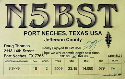 PART 7: - Mike had another appointment that brought him down this way on Tuesday, 2/17 so he stopped in and tried the KX-1 himself. He worked the first DX with the rig, hooking up with P49V in Aruba on 20M in an easy QSO. Let's turn the clock ahead a few days now in our story. After having his car inspected Friday morning, Mike returned around Noon that day for what we thought would be a quick job of finishing the KX-1 by installing the KB3080 module. NOT! After going smoothly for the most part in assembling the main rig, the small KB3080 board and even smaller LPF-1 board gave us more trouble than the whole main KX-1 assembly. 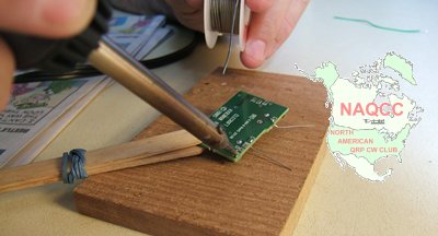 It started out easily enough with Mike soldering a couple of the wires that would mount the board to the main KX-1 board later on. It started out easily enough with Mike soldering a couple of the wires that would mount the board to the main KX-1 board later on.Things soon went downhill. The wires that connected the KB3080 to the KX-1 board were fine #24, and the stripper we had only went down to #22, so we had to improvise with an old adjustable stripper I had. It seems the opening got set just a tiny bit too small and when one of the wires snapped off, we examined it and found a nick where it had been stripped. The rest of the wires also had tiny nicks where they were stripped. So we wound up having to find some other wire in my junk box, and replacing the ones already soldered on the board. Then after doing that, we found a couple of the wires were not quite long enough to reach their mounting holes despite the fact we made them the exact length specified in the manual. So some more removing and replacing wires. That wound up taking a lot of time since it had to be done very carefully to avoid damaging the board or nearby components. 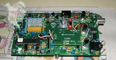 Finally after some time, we got the KB3080 board finished and mounted on the main KX-1 board as shown here. With our replacement vari-colored wires, we figure we must have one of the most colorful KX-1's around. We made the checks in the manual to be sure everything was working up to this point and it was. Finally after some time, we got the KB3080 board finished and mounted on the main KX-1 board as shown here. With our replacement vari-colored wires, we figure we must have one of the most colorful KX-1's around. We made the checks in the manual to be sure everything was working up to this point and it was.Now came the very tiny LPF-1 board, and it's smallness made for some very difficult assembly. Some of the very few parts had to be mounted and soldered so the solder connection was absolutely flush with the printed circuit board. This proved tricky, especially for holding the part in place while it was being soldered. We had this peculiar looking clamp which despite its appearance, worked fairly well. It was sensitive to heat though, and Mike had to solder very carefully. We didn't get a picture holding the LPF-1 board, but here it is holding the KB3080 board earlier with the tiny LPF board lying on the table. 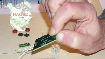 Mounting a tiny capacitor, relay, and two wires was accomplished, and then we went on to winding toroids. This was also time-consuming, and I'm sure if Mike ever buys another kit from Elecraft or if I decide to build a K2 some day, we will go with the pre-wound toroids offered by Elecraft. With a couple breaks for some food, and with Mike going along with me as I walked my neighbor's dog, Joe, it was now into the evening hours. The next step was mounting the little LPF-1 board on the main KX-1 board. This final step in the entire assembly process proved to be the most difficult of all. The components on the LPF board were so tightly packed, and the space on the main KX-1 board was so small, it proved an epic struggle to fit the board in correctly, let alone solder it. With the KXAT1 board installed, the components on it as well as the main KX-1 board virtually or actually touch those on the LPF-1 board, so the LPF-1 board has to be squeezed in somthing like trying to put toothpaste back into the tube. Then when the LPF is in place, it's impossible to visually check if anything is shorted or not connected properly as you can see from this picture. The tiny board with the two toroids and tiny capacitor visible is just to the left of the BNC connector at the right of the picture. 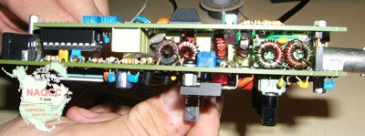 After we finally got it mounted, it was now somewhere around 8-9 PM and time to test it out. We did the receiver alignment for 80-20 meters and that worked OK. However things did not go so well for the transmitter testing. We had zero output from the rig although we could pick up the signal on my TS-480 in my shack upstairs on all 4 bands. Our guess at the moment is that we probably have a problem related to the LPF board. That's where we stand right now until the next time we get together to try to figure out the problem, and solve it. That will be March 5th. PART 8: - This is the final installment of our series of articles on the KX-1. However we will be mentioning results Mike will be getting with the rig from time to time here in the newsletters. Mike wrote a story describing the whole project from his viewpoint which we will get to in a moment after we tie up a couple loose ends. When we left you last time (remember that common closing line from the old radio serials?), the KX-1 was dead in the water and we ran out of time to figure out why. We thought it had something to do with the tiny little LPF board, but couldn't figure out what at that time. Early in the morning of the day Mike was coming down to finish (hopefully) the project around Noon, I was sitting around waiting to help take my neighbor's dog Joe to the vet, and decided to look at the kit. More or less, the problem jumped right out at me. I noticed a solder pad near where the LPF board was mounted had an empty hole with some remaining traces of solder on it like we had removed a part when adding the LPF board. I decided to check just why it was that way and found out that was where the input to the filter should be. We had removed the old toroids from that area as instructed prior to mounting the LPF board. OK, well where was the input, I wondered. After examining as best I could in the crowded area, I found it in another solder pad. That was obviously the problem. At the end of our previous long day of work, we put the lead in the wrong hole. I waited for Mike to come before attempting to fix it so I could point out to him what we had done, and to give some tips on finding such problems for future reference. Without further ado now, let's get to this from Mike KC2EGL to wrap up the series and to hear how we found one more problem and fixed it also. From Mike KC2EGL: This was my first attempt at building any type of a Amateur Radio Kit. At the start of this project I was very green when it came to using a soldering iron. My only experience with a soldering iron was installing three accessories into my Kenwood TS 480SAT (which resides with John K3WWP at the moment). For starters I thought it would be a tougher project. Elecraft has taken so much of the worry out of building a kit. They have gone above and beyond with the way they lay out the builders manual. Of course there are a few places where you may have to read the instructions more than once just to understand the method behind their madness. If you decide to build a kit from Elecraft please try to remember one thing. DON'T QUESTION THE MANUAL! This was a constant theme between John and myself. We would finish work on one part of the PCB thinking "why do we have to do it like this?". Only to find out a few minutes later that there is no option. Whenever this happened John and I would say in stereo "don't question the manual". We started out assembling two Elecraft 20W dummy load's. One for the KX-1 and one for my K-2. This turned out to be a good exercise for a rookie with a soldering iron. After the dummy load's we did our inventory of parts for each component of our kit. There is the proverbial boatload of parts for this kit. I can only imagine how long a inventory for the K-2 would take. The inventory we did took the whole day. There are plenty of very small parts with very tiny markings. Our kit included the basic KX-1 (20/40M transceiver), Auto antenna tuner, and 30/80M module to make the rig a four band rig. We planned on starting with the smaller components and working our way up to the KX-1. That plan fell apart right from the start. The smallest component was the 30/80M module. After browsing the instructions we found that there would be a few modifications we would have to make to the main PCB on the KX-1 in order to get the 30/80M board to work properly. So we went ahead and assembled the auto antenna tuner. It is very straight forward. The hardest part was winding the toroids. Next time I will order pre-wound toroid's. It was a very good learning experience winding my own toroids. Now that I know what has to be done I will make sure I NEVER have to do it again if at all possible. After the auto antenna tuner was complete we started on the main board. We jumped from one corner to another. From the front side of the board to the back side. And yes sometimes we would look at each other saying "Don't question the manual". Of course we needed a few days of work to complete the main board. We never did count how many items went on the main board. All I know is that there are a lot of parts that must fit on the board. The hardest thing was making sure that we had the proper height for each component. This is a critical step with this kit. If you do not keep all the components at or below the maximum height you will not be able to install the other options properly. After each group of components are installed the manual calls for testing what you have already assembled. All of the testing can be done with a multimeter. They are very straight forward and will tell you what is and what is not working properly. One tool that is a necessity is a insulated tuning tool. I found a package of old insulated tuning tools that are used for CRT TV sets that were in stock at a Radio Shack. We were able to put one of them to use. Unfortunately we needed a tool with a rather small flat tip that would fit in the port hole provided for access to the receiver adjustments. We improvised by using a precision flat tip screwdriver wrapped in electrical tape. This let us adjust each band of the receiver for a peak noise level. The hardest part of this project for us was the assembly of the 30/80M board. There are a few modifications you have make to the main board in order to install the 30/80M board. This is a step that will test your faith in everything. If this were a piece of real estate it would be a very heavily populated neighborhood. The height tolerance with this board is even more precise than any of the other boards. And once you get it installed it is impossible to see if there is anything that may short out the system. After a bit of coaxing we were able to get the board installed on to the main board. First we had to remove two toroids to make room for the 30/80M board. This is where I had a little trouble. I installed one of the toroid leads into the wrong hole on the main PCB. This mistake gave the rig a whopping total of ZERO watts output. I did not find the mistake. John found it. Lucky for us it was a minor fix. It took a bit of time to make the fix but it was minor. The assembly and installation of the 30/80M board was much more difficult than we had anticipated. We thought everything was complete. All of our testing went without a hitch. This included a transmitting test for each band. John would listen for my signal on his rig in his shack while I sent K3WWP DE KC2EGL QRT K through one of the dummy loads. We then headed up to his shack to give it a live test with his antennas. We thought we had finished our project only to find that the rig would not tune properly using the auto antenna tuner. When the rig was completely enclosed the tuning would get us a SWR of 6.7 at best. We found that if we tightened the thumbscrew on the right hand side all the way down the auto tuner would not function properly. We decided to leave it a bit on the loose side so it would tune up. Yesterday (March 6 2009) as I was just about to fire off an email to Elecraft to request an order of the 30/80M board we had so much trouble with, I find a email from John letting me know that he found the problem. Again it was a minor fix. One of the grounding leads from the little LPF board was not as snug as it should have been. It was touching a pad on the ATU thus creating a short. John adjusted the lead and presto! We now have a working KX-1. I would say it took us a total of thirteen hours to complete from start to the final troubleshooting fix. So far we have 'Christened' three of the four bands. John is trying to get a QSO on 30M. We have already made one DX QSO (P49V) with it as well. So we are off and running with the KX-1. This is a very good project for someone who is new to kit building. That is if you have a Elmer to assist you. This kind of project will help one learn how a radio works. I now have a greater understanding on how my other rigs work. Now I need to find another project to work on. Maybe John will think of purchasing a K-2. That would be a fun project to work on. I would like to thank my very good friend John Shannon K3WWP for helping me with this kit. I would not have been able to work on this project without his assistance. It was very rewarding for me (K3WWP) to watch Mike develop as a kit builder over the several sessions we had to work together on the kit. I haven't built a kit in many years now, and the experience left me with the desire to do it again. Perhaps as Mike suggested, I will try a K2 sometime in the future, but probably not until the fall or winter at the earliest as I am now getting the urge to get back to my fishing and gardening as well as taking longer outdoor walks. And now "The rest of the story" (to borrow the catch phrase of the late greatly beloved radio commentator Paul Harvey). 30 meters has now been 'christened' as Mike puts it. I worked K9VSO in Wisconsin and then HK0/EA7HEJ on San Andres Island. I believe we showed that by being careful it was not necessary to go to extremes about avoiding electrostatic discharge damage. However we do recommend that you think about the matter seriously if you are going to attempt building a kit that involves static sensitive parts. If you don't trust yourself to be careful enough, eliminate any doubt by investing in a grounding wrist strap, anti-static mat, and grounded tip soldering iron. Also be careful about your clothing. Don't wear a sweater that is susceptible to static buildup, for example. Keep sensitive parts in their anti-static packing until needed. Only use styrofoam egg cartons to separate and store parts that are not at all static sensitive. It's costly and time consuming to have to replace a static damaged part. I commend Elecraft on the excellence of their products and the wonderfully detailed and accurate assembly and operating manuals. Also their quick and efficient support services. I'd like to name all the support folks here, but the only one I know by name is Gary Surrency AB7MY. Oh and these folks, who mostly work anonymously and don't get enough thanks: 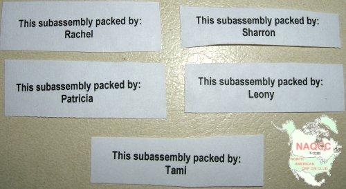 And to close, the finished product, top, bottom, and in its case: 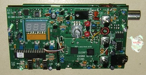 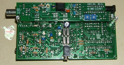 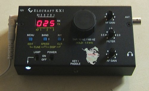 Good Day! NOTE - This KX-1 project article and included pictures are the exclusive property of the NAQCC, and may not be copied in whole or in part by anyone. You may link to this article if you wish, as long as the NAQCC is given full credit as the source of the information and pictures. |